I’m working on a prototype for what I’m calling the Bullshit Ball. To be fair, this was an idea stemming from our recent Making Digital Work Conference where Edward Boches suggested a box be present in meeting rooms that could relay whether members in the room thought the person speaking was full of shit or not.
I decided this was a noble enough idea to spend a week trying to build. I’m not finished with it yet, but as part of the invention requires a glowing ball with different hues of light, I’ve come up with an interesting way to control Tri-color LEDs with a little high school trigonometry…
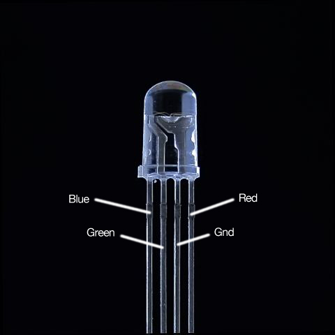
Tri-color LEDs operate with one ground wire and three different leads for (blue, red and green).
The objective is then to create some sort of fade-in / fade-out situation where as once color is fading out, another color is fading in. This will create different hues and provide a relatively seamless transition between one color and the next. I was experimenting with ways to increment one color whilst decrementing another when it dawned on me that all I need were some wave forms. I turned to trig 101 for the answer.
Basically, the equation goes something like this:
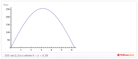
- Set the amplitude or “height above zero” to 255 to represent the values of PWM on an arduino.
- If I want blue to be the center value, then take the sin of the value for blue.
- Divide the value of blue by 1/2 since we only want one half of a wave.
And you end up with a wave like this:
Green:
Green:
NOTE: I use percentages in the code example because I’m making this LED behavior for the bullshit ball, which will return a percentage of votes.
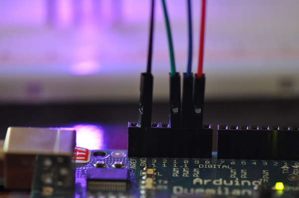
Hardwiring…
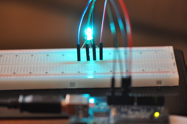
And…
Now for some code…
/*

AUTHOR: Michael Newell
SITE: https://iwearshorts.com/

Based on the original FADE sketch under the Basics tab of default arduino sketches.

No License, feel free to do whatever you want with this.

This sketch articulates how to fade different hues of a tri-color LED in and out continuously.

*/

float fadeAmount = 0.01;    // how many points to fade the LED by
float percentage = 0.98;    // where to start

void setup()  {
  Serial.begin(9600);
  // declare pin 9 to be an output:
  pinMode(9, OUTPUT);
  pinMode(10, OUTPUT);
  pinMode(11, OUTPUT);

}

void loop()  {

  // change the percentage for next time through the loop:
  percentage = percentage + fadeAmount;

  analogWrite(9, setPin9(percentage)); // red
  analogWrite(10, setPin10(percentage)); // blue
  analogWrite(11, setPin11(percentage)); // green

  // reverse the direction of the fading at the ends of the fade:
  if(int(percentage*100) == 1.00) {
    Serial.println("changed to a negative fadeAmount");
    Serial.println(fadeAmount);
    fadeAmount = -fadeAmount;
  }

  if(int(percentage*100) == 99.00) {
    Serial.println("changed to a negative fadeAmount");
    Serial.println(fadeAmount);
    fadeAmount = -fadeAmount;
  }

  // wait for 30 milliseconds to see the dimming effect
  delay(300);
}

int setPin9 (float percent) {
  if(int(percent*100) < 49.00 && int(percent*100) > 1.00) {
    return 255 * cos( .5 * (PI * (percent * 2) ) );
  } else {
    return 0;
  }
}

int setPin10 (float percent) {
  return 255 * sin( .5 * (TWO_PI * percent) );
}

int setPin11 (float percent) {
  if(int(percent*100) > 50.00 && int(percent*100) < 99.00) {
    return 255 * sin( .5 * (PI * (2 * (percent - .5) ) ) );
  } else {
    return 0;
  }
}
You can also check out the source on Github.


I spent all day trying to sort this out for myself, and only came upon this page because my own design was not working and a quick google for the pinout of a tricolor LED brought me here. At least I know I’m not crazy for trying to figure it out.
Hey There. I discovered your blog the use of
msn. This is a really neatly written article. I will be sure to bookmark it and come back to learn more of your helpful info.
Thank you for the post. I’ll definitely comeback.